


12mm
4. Check the marker line on the coupling is positioned a little forward of the corridor connection or buffers. It may be necessary to trim the coupling pocket or the shoulder of the coupling bar back a little.
5. In some cases the delta part of the draw bar may foul the wheels, if so then file the delta into a T shape.
6. When you are satisfied with the location of the unit and any other modifications you may have done, the unit may now be glued to the floor of the carriage.
7. The bogies are replaced so that the draw bar sits centrally in the slot cut into the end of the bogie.
8. Set the coupling pocket so that the bottom of the female coupling is 5.5mm above the rail.
The Couplings
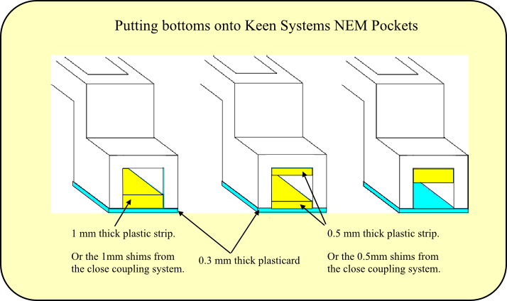
1. Downwards adjustment of the couplings is possible by fitting shims to the coupling pocket before fitting the coupling bar. One 0.5mm shim and one 1mm shim is provided on the frame.
2. Roco or Fleichmann couplers may be fitted if you require auto coupling and uncoupling of your coaches.
The Close Coupling System will enable British outline ready to run and kit built 00 model railway carriages to run buffer to buffer and still run on Hornby radius 1 curves.
The unit is fitted to the floor of the carriage behind the buffer beam and a slot is cut in the end of the bogie to allow the draw bar to move independently from the bogie.
The height of the coupling plate is downwards adjustable with the aid of the shims supplied.
The draw bar will accept either the Roco or Fleischmann close coupler device if auto coupling is required.
You will need a razor saw, scalpel, 6inch steel rule, set square and glue to fit the unit.


GENERAL FITTING INSTRUCTIONS
Setting the Buffer Height
1. Buffer height measured from the top of the rail to half way through the buffer head of the railway carriage:
LMS IS 3ft 51/2 ins,
GWR is 3ft 6ins,
LNER is 3ft 53/4 ins,
Southern is 3ft 6ins,
Pullmans 1923 onwards is 3ft 7ins.
All of which averages out to a scale height of 14mm.
2. Most Hornby Railroad coaches have a buffer height 2mm too high. This height can be reduced by filing the bogie mount on the chassis down to the level of the sole bar.
3. Other manufacturers have the buffer height too low and need to be raised by inserting spacers of washers or plasticard between the bogie and the chassis mounting.
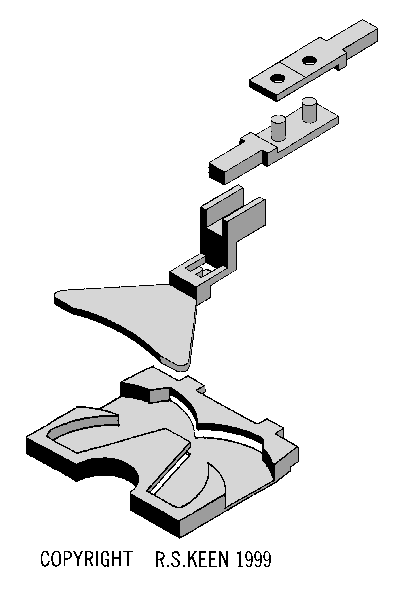
The Coupling Unit
1. Slide the draw bar into the base plate from the side.
2. Fit a coupler to the draw bar with marker line uppermost, but do not glue into place yet.
The Bogies
1. Remove bogies from carriage.
2. Remove wheels from bogies.
3. Remove coupling from bogies and using razor saw and scalpel cut a wide slot in end of the bogie frame.
4. Replace wheels.
The Chassis
1. Remove any raised detail from under side of chassis between the buffer beam and the bogie pivot.
2. Place the base plate to chassis behind the buffer beam. The base plate may need to be reduced in width, if so scribe marker lines on the back of the base plate with a calliper gauge as a filing guide. Remove the tabs if they are not needed.
3. Set the leading edge of the base plate 12mm back from the corridor connection or buffers which ever is the furthest forward.


Tail
Blade (female)
Marker Line
Blade (male)


SLIDING DRAW BAR
Coupling Pocket
Drop Arm
Forward Arm
Finger
Delta Plate


BASE PLATE
Tab
Leading Edge
Forward Guide
Forward Shoulder
Return Guide


Trailing Edge


FLAT PLATE COUPLERS

COPYRIGHT R.S.KEEN 1999


Ease the locating holes of the female coupling plate and countersink the top of the hole to make coupling the male plate easier.


The Flat Plate Coupler